Motivation
 The connection between textiles and the cosmic web of dark matter was partially inspired by the thread-like appearance of filaments in images like the one to the right (see also scientific background). Rather than creating the most accurate representation of the simulated dark matter structures, we aim to connect dark matter and three-dimensional textiles because mapping the cosmic web into two dimensions reduces it to a visualization akin to the images shown on this website.
However, the output of our simulations is essentially a cubic grid of dark matter density. Our goal is to extract fundamental, three-dimensional shapes from this data that can be translated into a weavable pattern. Given the results of our 3D weaving experiments, we restrict these shapes to halos (woven spheres) and straight-line filaments (threads between the halos). This page describes the process of extracting these shapes from a simulation and mapping them onto a two-dimensional weaving pattern.
Simplifying the simulation data
We begin by choosing a specific section of a simulation. In this example, we use a cube around a massive halo, 230 million light years on a side (shown in projection in the blue image above). The halos (dense clusters of dark matter) are extracted with a so-called halo finder program, we use Rockstar. The filaments of the cosmic web are also of scientific interest and computer software to extract them from a density field already exists; we used a code called Disperse for this purpose.
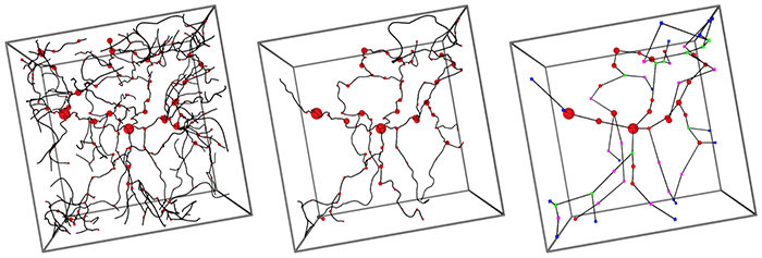
The procedure by which we choose halos and filaments to translate into textiles depends on the specifics of the final installation. Here, we show the data used in our Phase I installation where we represented both halos and filaments. The three images above show the extracted filaments (black lines) and the halos that lie along those filaments (red spheres). In the left image, we recognize the two largest halos from the image at the top. However, the filamentary structure shown on the left is still too complicated for our purposes. For simplicity, we restrict ourselves to only the most prominent filaments and halos (center). Furthermore, we convert the filamentary structure into a set of anchor points (right image), namely halos (red), end points (blue), branching points (green), and intermediate anchors (pink). The filaments between those points are now represented by straight lines.
 Weaving
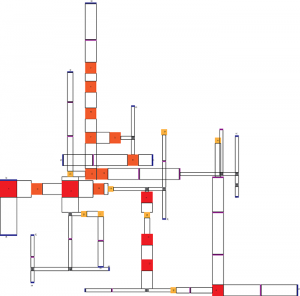
At this point, we finally merge simulation data and weaving. We map the halos and filaments (if applicable) onto a rectangular, weavable arrangement. The image shows the layout of our Phase I weaving which had an area of 6 square meters and was re-oriented to accommodate the limits of the weaving loom. Here, halos are represented as squares (red, orange, and yellow) and filaments as empty areas. The halo rectangles are replaces by complicated weave patterns that create sphere-like shapes when pulled open. For other installations, we have woven the halos as separate pieces.
Our weavings are produced on industrial weaving machines at the TextielLab in Tilburg, Netherlands. The gallery below shows some photos taken during a visit when much of the spherical weave structure was developed.


If you are looking for additional information, the process described on this page is discussed in much greater detail in our first paper.